Create a GPS Data Logger Using The Arduino
Recently I have been developing an application that leverages GPS tracking. The high-level concept is to track mobile assets via GPS tracking. Each asset will have a GPS unit installed that logs its location. With the availability of low cost GPS this is becoming an every day reality. Many companies already use GPS to track and monitor their assets. In this post, we explore one option for the GPS tracking hardware.
There are really a two options for GPS tracking hardware: dedicated or shared GPS hardware. There are more and more devices (especially phones) that have GPS hardware. One solution is to write software that can be deployed to these devices and share the common GPS hardware. This is a great solution and I hope to explore this in later blog posts.
The other option is to develop your own dedicated hardware. Staring from scratch can be very daunting and expensive. However, there are a number of developer kits / boards that can spring board your development. In this post, we explore using the Arduino development kit to provide a quick and easy solution to our own dedicated hardware.
Meet The Arduino
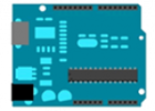
After doing some investigation on the internet I selected the Arduino along with a GPS shield as the development hardware. The Arduino is a tool for the design and development of embedded computer systems. It consists of a simple open hardware design for a single-board microcontroller. The Duemilanove Arduino board is shown below:
There are two main reasons I chose the Arduino over other options:
- The main board (shown above) is expanded by plugging in addition hardware called “shields”. There is an abundant number of shield options including a GPS Shield.
- There is an existing ecosystem (suppliers, shields, libraries) and a strong developer community for the Arduino board and shields.
There is an embedded board that is compatible with the Arduino shields but is programmed using the .NET Micro Framework called the Netduino. The community is growing for this board, but I was not able to find the support that I (an embedded newbie) needed to get going. After I get experience with the Arduino and the GPS shield, I will try to convert it to use the Netduino.
The Arduino IDE
The IDE for Arduino development can be downloaded and come with many examples. Here is a screenshot of the IDE including example code to blink and LED (light emitting diode).
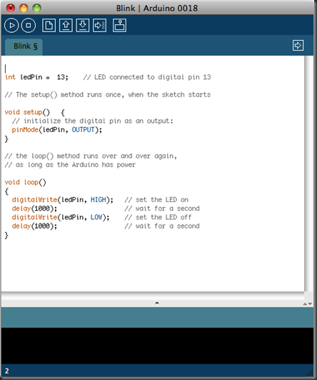 At a basic level, there are two main functions that a developer needs to “fill in” to get the Arduino working. The ‘setup’ function runs once. The ‘loop’ function repeats as long as the Arduino has power. The ‘setup’ / ‘loop’ combination creates a program called a ‘sketch’. Sketches are uploaded to the Arduino hardware via a USB cable. There are Windows and Mac versions of the IDE.
A developer creates a sketch, uploads it to the Arduino, and debugs the program using the USB as an umbilical cord. Once the program is ready to be deployed, the final version is uploaded and the Arduino can be run off of a 9 volt battery. This workflow is developer friendly and promotes experimentation.
GPS Shield
The GPS shield that I selected not only integrates with a GPS module but also includes data logging to a SD card. One surprise that I had was that the GPS shield looked like this when it came:
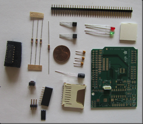 Don’t let this scare you. The soldering is really easy and the instructions are extremely clear. After assembly, the shield looks like the following:
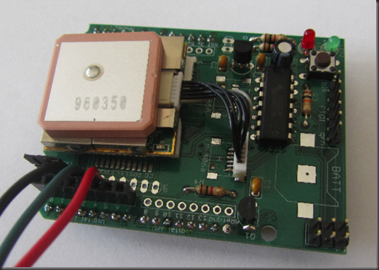
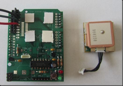 The assembled shield is on the left and the GPS module is on the right. The GPS module plugs into the board and sits on the non-conductive double-sided taped four white pads.
On the bottom side of this board (not shown) is the SD card slot. This is used by the embedded system to persist the GPS data streamed from the GPS module.
Programming the Arduino / GPS Shield
The GPS shield site provides all the libraries and step-by-step instructions on programming the GPS shield / Arduino combination. Following these instructions, will have the hardware up and logging GPS data points in very little time. I did not run into any issues and will leave the details to the above site.
Testing
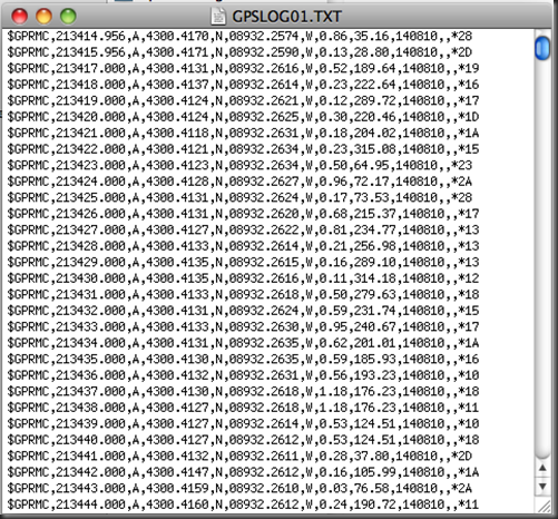
Once I assembled and programmed, I took the Arduino hardware on a test drive. I did not alter the provided Arduino sketch at all. By default, GPS points are logged to the SD card every second. There are suggestions to extend battery life by logging less often and shutting down diagnostic systems. The data is logged in text files. Opening one of these files you will find something like the following:
Each “GPRMC” line is the recommended minimum data set and is transmitted by most GPS devices. Each line can be decoded into: timestamp, latitude, longitude, speed, bearing, and status information.
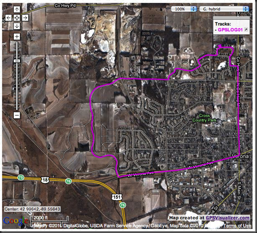
At the GPS Visualizer site you can upload the file and have the data displayed on Google Maps. Here is a screen shot from my short trip:
Summary
I found the GPS unit was able to get a fix on the satellites even inside my house. Overall I am very pleased with this hardware. I will be exploring a bit with this hardware and learning more about the software.
The ultimate goal is to have GPS hardware to collect data for the Truck Tracker application. There is a wireless shield that I think I can add to the board to allow the data logged to the SD card to be wirelessly posted to a web service. For now, I am okay manually uploading the text files.
I am extremely pleased with how easy it was to get started with the Arduino. If you are looking for a simple embedded solution, check out the many examples.

A hitech job, but still interesting! gud post!
Thank you, I have recently been searching for information about this topic for ages and yours is the best I have discovered so far.
Really nice post,thank you
Thanks for the post
Great work keep it coming
Good day!This was a really outstanding post!
I come from itlay, I was luck to approach your theme in bing
Also I learn much in your topic really thank your very much i will come later
It’s nearly impossible to find knowledgeable individuals on this subject matter, nevertheless you sound like you know what it is you’re talking about! Thank you…
Good job, man!
Thank you very much…. this whole series is really helpful and I appreciate you spent time and shared your knowledge with us…. Thanks a lot….
do you think it’s possible to add on top of what you just built an XBee radio.If so,could you provide more details about what it’s necessary to accomplish this.
Maybe,another post devoted to this idea.Thanks,anyway.